This practical CNC machining design guideline shares easy-to-follow DFM tips tailored for engineers and designers. Different from standard checklists, we focus on real machining challenges, including dedicated advice for milling, turning and fragile cantilever structures. Follow these rules to create fully manufacturable parts, control your budget and shorten lead times for both prototypes and mass orders.
Why Design Rules Matter for CNC Machining
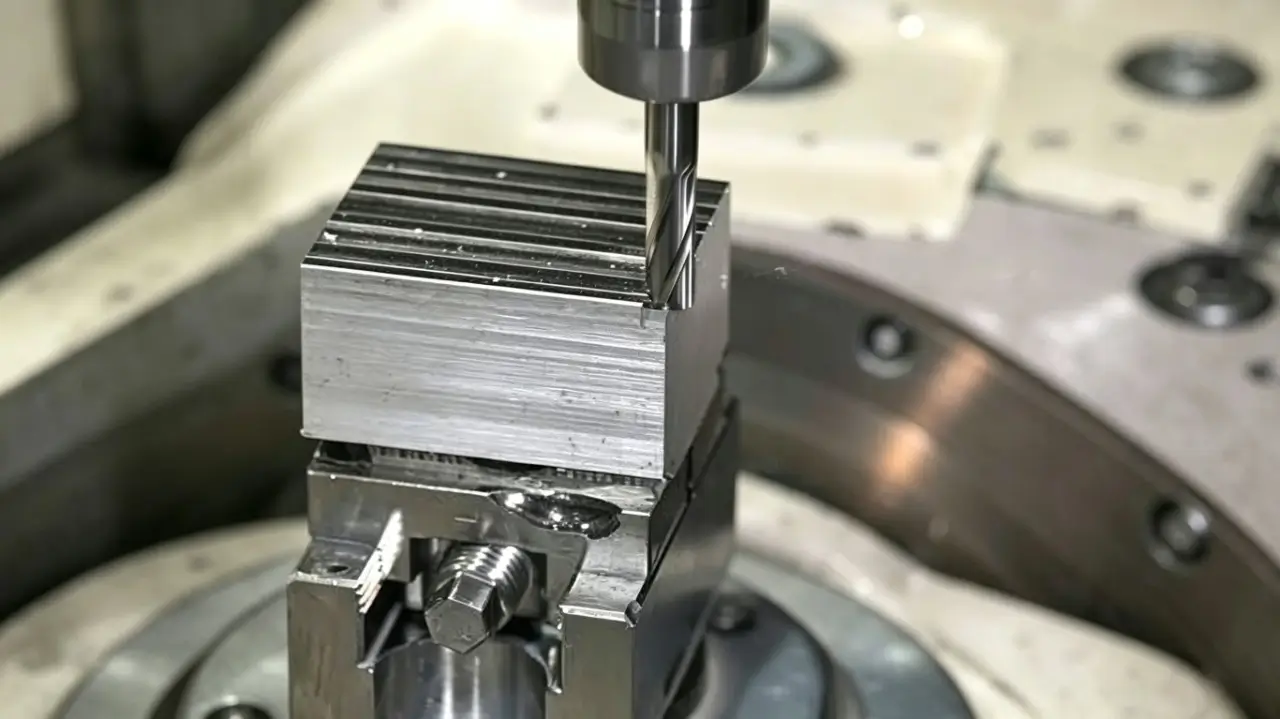
Unlike additive manufacturing, CNC machining is a strict subtractive process that relies on physical cutting tools to remove material. Every tool has fixed dimensions, reach limits and cutting constraints that cannot be bypassed during production.
Many new product designs prioritize functionality and appearance but ignore manufacturability. Features that look feasible in CAD software can cause tool chatter, tool breakage, uneven surface finishes and high scrap rates on actual machines.
Following standardized CNC design rules helps engineers avoid unmanufacturable structures, reduce secondary processing and stabilize batch quality. It is the most efficient way to lower CNC machining costs and shorten lead times without sacrificing part performance.
Basic Rules When Designing for CNC Machining
Following universal basic rules at the initial design stage can greatly simplify machining processes, cut tooling costs and reduce unnecessary operational complications.
Prioritize geometries that can be processed with large-diameter standard cutting tools. Standard tools eliminate the need for custom tooling, speed up material removal and shorten overall production cycles.
Control the depth of internal cavities strictly. As a general rule, the depth of any cavity shall not exceed four times its width. Excessively deep cavities will raise the difficulty of chip evacuation and tool control.
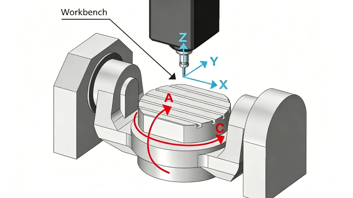
Take the machine axis configuration and main moving directions into full account. Align part features with the machine’s primary working directions to avoid tool access dead zones.
For engraved text on part surfaces, do not use fonts smaller than 20 points. Oversized tiny text is prone to incomplete engraving and blurred characters during processing.
Design Restrictions for CNC Machining
CNC machining has inherent limitations derived from cutting tools and machine movement. All designs must comply with these two core constraints to ensure smooth production.
Tool Geometry Limitations
Nearly all standard CNC cutting tools are cylindrical with fixed effective cutting lengths. When removing material, the tool’s shape will be reproduced on the workpiece.
For this reason, it is impossible to create perfect sharp internal corners with conventional milling tools. All inner corners will naturally form radii matching the tool profile, no matter what size cutter you select.
Tool Access Limitations
Most standard CNC machines cut materials from the vertical direction. Tool access becomes a critical challenge for parts with a large depth-to-width ratio or hidden inner structures.
Features that cannot be reached from the top direction are hard to machine with common 3-axis equipment. You can align part features with the six principal directions of the machine to ease tool access. If complex undercuts are required, 5-axis CNC machining is the ideal solution.
CNC Machining Design Guidelines
The manufacturability of CNC machined components is fundamentally governed by the geometric design of individual features. Hole sizing, structural wall thickness, cavity depth limit, thread specification and tolerance grading collectively dictate tool selection, cutting rigidity, chip evacuation and dimensional repeatability. Adhering to standardized CNC design rules eliminates costly secondary operations, suppresses cutting chatter, stabilizes batch consistency and reduces overall part manufacturing cost.
Wall Thickness Design
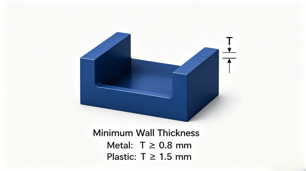
Wall thickness plays a critical role in determining machining stability, dimensional accuracy, and overall part quality. Thin walls are more likely to vibrate under cutting forces, resulting in chatter marks, dimensional deviations, and potential deformation during machining.
For most metal components, a minimum wall thickness of 0.8 mm is recommended. Plastic materials generally require thicker walls, with 1.5 mm considered a practical minimum. If thin-wall features are unavoidable, designers should consider additional support structures and lighter cutting parameters to maintain stability throughout the machining process.
Internal Edges & Corner Radii
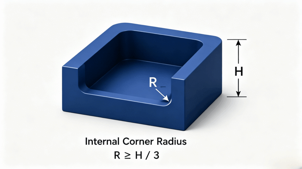
Because CNC milling cutters are cylindrical, perfectly sharp internal corners cannot be produced using standard machining processes. Every internal corner will naturally include a radius corresponding to the cutting tool diameter.
As a general guideline, the internal corner radius should be at least one-third of the cavity depth. Larger corner radii improve tool engagement, reduce cutting loads, and enhance surface finish quality. If a design requires square internal corners for assembly purposes, dog-bone reliefs provide a practical solution without compromising machinability.
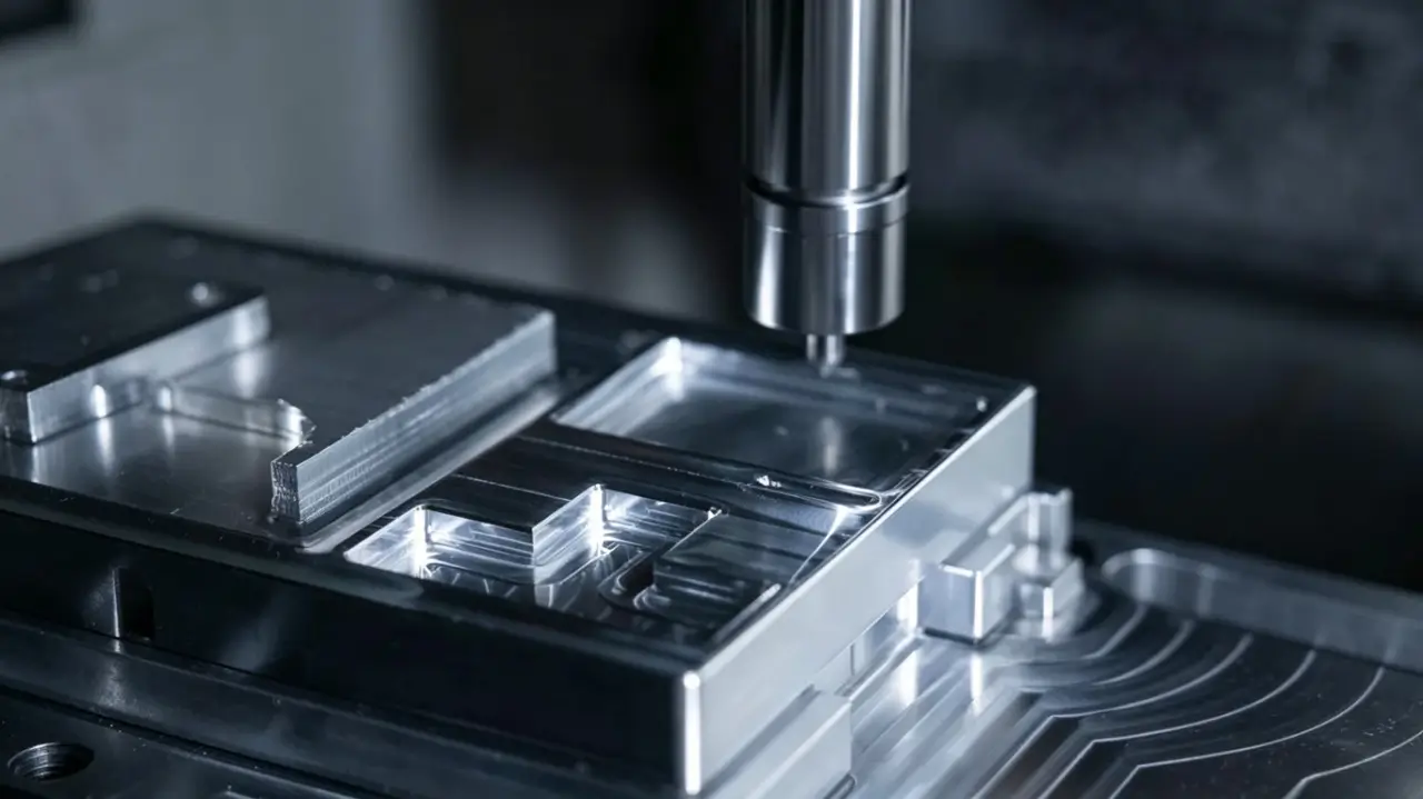
Cavities and Pockets
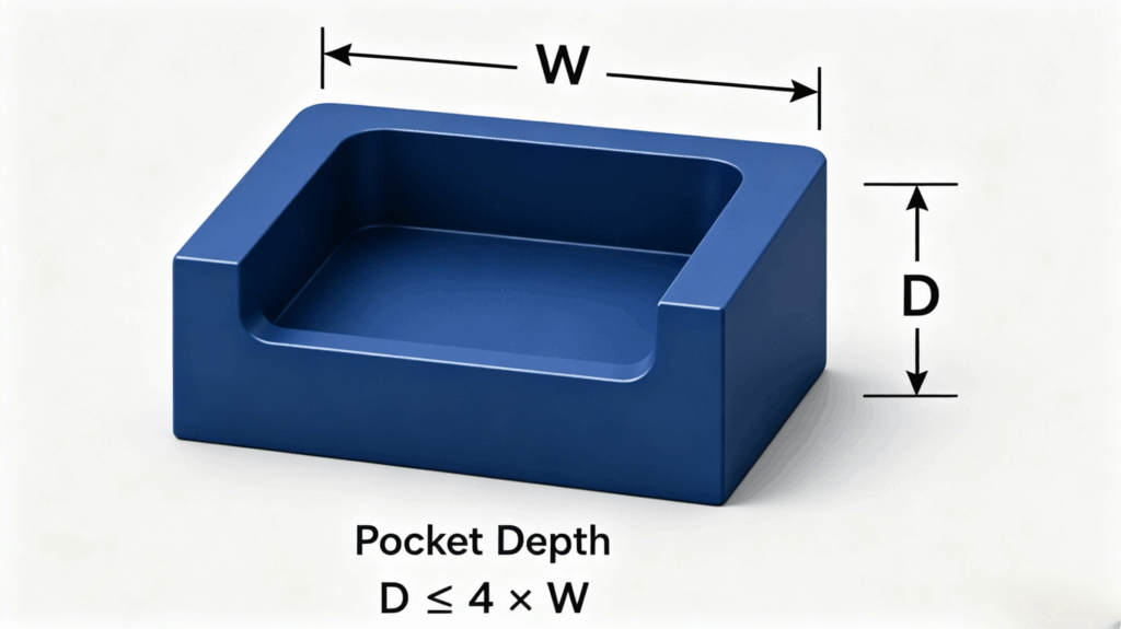
Cavities and pockets are common features in machined components, but excessive depth can significantly increase machining difficulty. As cavity depth increases, tool deflection, vibration, and chip evacuation issues become more pronounced.
A widely accepted guideline is to limit cavity depth to no more than four times its width. For deeper features, stepped pocket designs often provide a more manufacturable alternative. In production environments, cavities exceeding a 6:1 depth-to-width ratio frequently require longer tooling, custom cutters, and additional machining time.
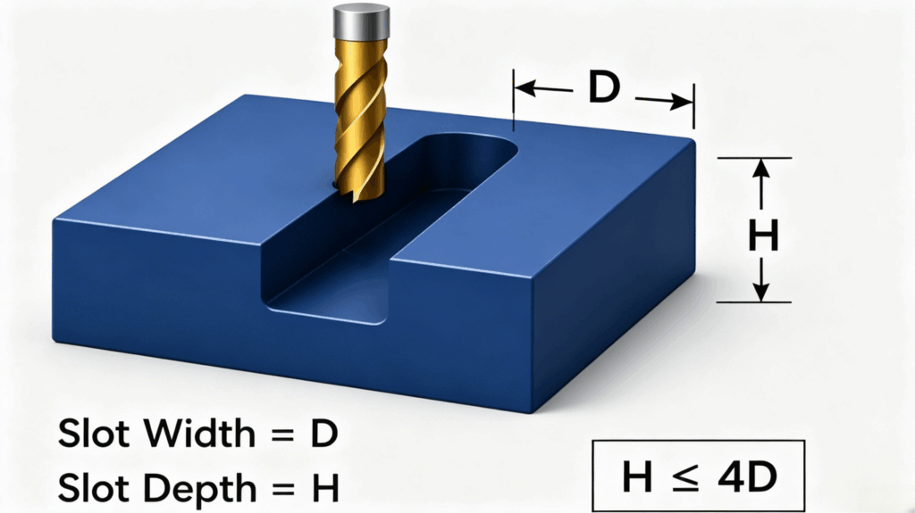
Slot Design
Slots are generally more difficult to machine than open pockets because chips have fewer escape paths and cutting tools experience higher side loads. Deep and narrow slots can quickly lead to vibration, poor surface finishes, and premature tool wear.
Whenever possible, slot widths should match standard end mill diameters. As a practical recommendation, slot depth should not exceed four times the slot width. Designing slots around standard cutter sizes helps reduce machining complexity and improves overall production efficiency.
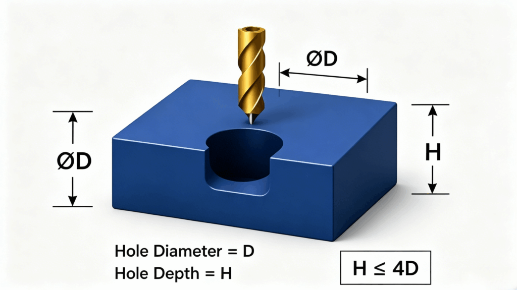
Hole Design
Holes are among the most frequently machined features and should be designed around standard drill sizes whenever possible. Using standard metric or imperial dimensions minimizes tooling costs and improves dimensional consistency.
Although holes larger than 1 mm can typically be manufactured, standard drill sizes are strongly recommended for precision applications. The recommended depth of a standard drilled hole is up to four times its diameter. For specialized deep-hole applications, ratios of 10:1 are common, while dedicated deep-hole drilling equipment can achieve significantly greater depths when required.
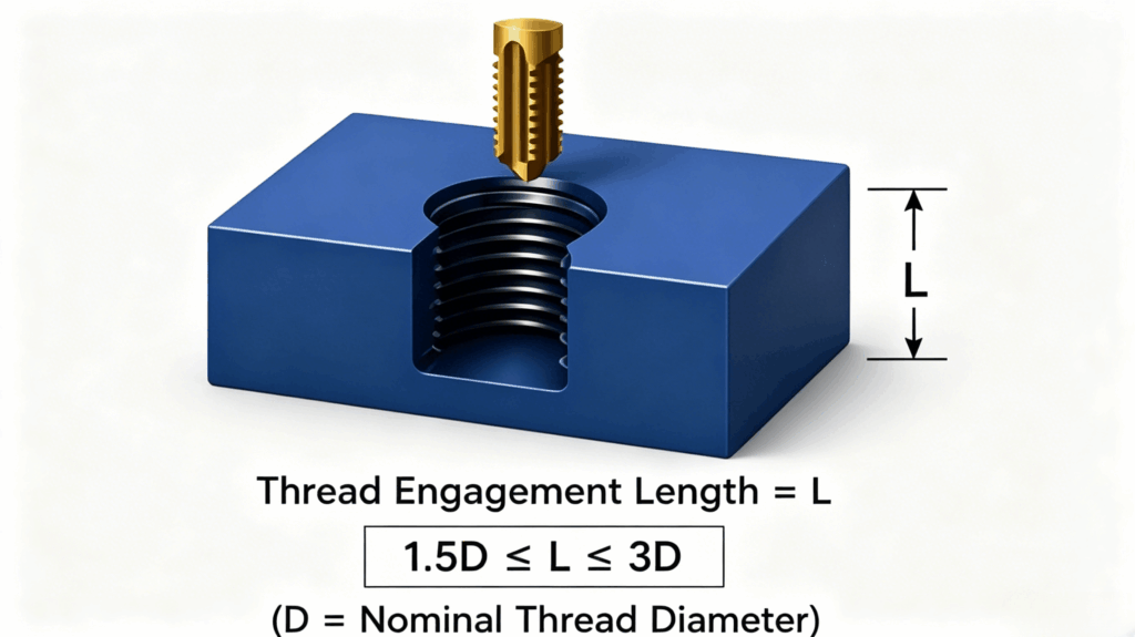
Thread Specifications
Threaded features should be designed with both functionality and manufacturability in mind. Very small threads increase the risk of tool breakage and often require slower machining speeds.
M2 is generally considered the minimum practical thread size for CNC machining, while M6 and larger threads provide the best balance between strength and manufacturability. The minimum effective thread engagement length is typically 1.5 times the nominal thread diameter, while a length of 2 to 3 times the diameter is often ideal for most applications.
For blind threaded holes, sufficient clearance should be provided below the threaded section to accommodate tap geometry and chip accumulation during machining.
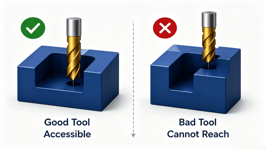
Undercuts and Tool Accessibility
Tool accessibility is one of the most important considerations in CNC machining design. Features that cannot be reached directly by standard cutting tools often require additional setups, specialized tooling, or multi-axis machining.
Undercuts, recessed features, and hidden geometries should only be used when functionally necessary. Designing features that are accessible from standard machining directions reduces setup complexity, lowers production costs, and improves manufacturing efficiency.
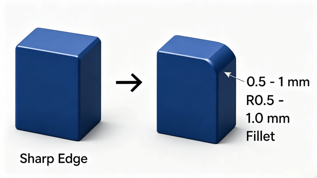
Chamfers & External Fillets
Sharp external edges and unfilleted outer corners create heavy burrs during cutting and raise risks of chipping, scratching during assembly and handling. Uniform edge finishing can eliminate extra manual deburring steps.
Standard 45° chamfers between 0.5mm–1mm are the most cost-effective choice for hole openings, step shoulders and outer edges. If no specific chamfer size is marked on drawings, manufacturers will automatically break all sharp edges as standard operation.
Add small transitional fillets to all external corners. Outer fillets disperse mechanical stress concentration and match the natural contour of peripheral milling cutters, avoiding sharp fragile corners that easily get damaged in mass production.
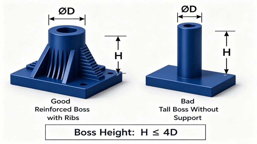
Tall Bosses & Cantilever Ribs
Tall narrow protrusions, standalone cylindrical bosses and unsupported cantilever ribs suffer severe resonant vibration under lateral cutting loads. Vibration creates uneven surface texture, out-of-tolerance dimensions and high scrap rates.
Control the height of all raised features within 4 times their base width. When tall structural protrusions cannot be removed, add triangular gusset ribs and root fillets to connect bosses to the main part body and reinforce structural rigidity.
Tolerance Design
Tolerance requirements have a direct impact on machining cost, production speed, and inspection effort. While modern CNC equipment can achieve extremely tight tolerances, tighter specifications generally require additional machining operations and more extensive quality control.
For most machined parts, a standard tolerance of ±0.125 mm is sufficient. Critical assembly surfaces, bearing seats, and sealing features may require tighter tolerances such as ±0.05 mm or ±0.01 mm. Designers should only specify tight tolerances where they are functionally necessary to avoid unnecessary manufacturing expenses.
| Tolerance Range | Relative Manufacturing Cost |
| ±0.125 mm | Low |
| ±0.05 mm | Medium |
| ±0.01 mm | High |
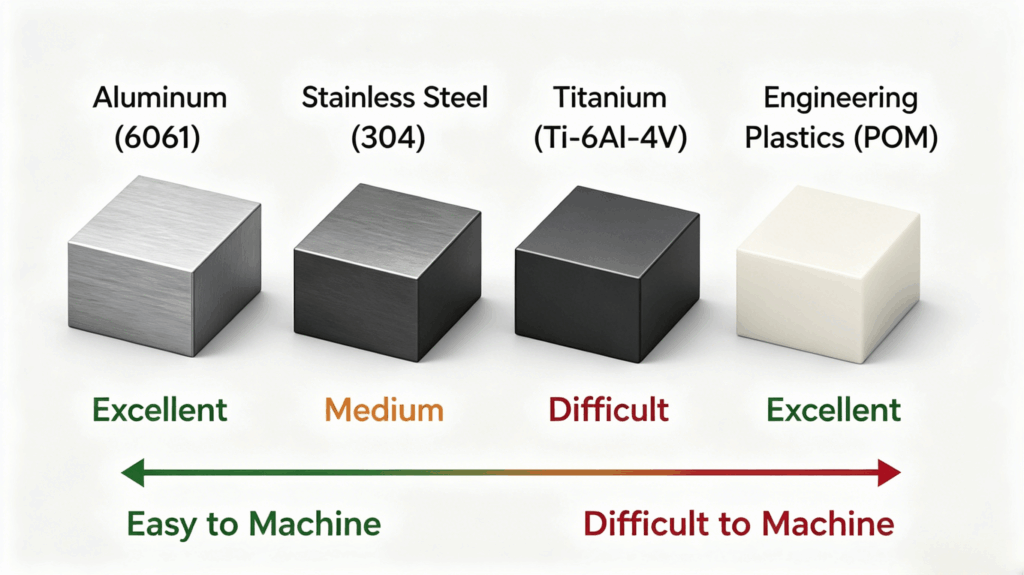
Material Selection Considerations
Material selection influences machining speed, tool life, achievable tolerances, and overall production cost. Different materials respond differently to cutting forces and heat generation during machining.
Aluminum alloys are among the easiest materials to machine and are widely used for general-purpose applications. Stainless steel provides excellent corrosion resistance but requires slower cutting speeds and generates higher machining costs. Titanium alloys offer outstanding strength-to-weight ratios but are significantly more challenging to machine due to poor thermal conductivity and accelerated tool wear.
Engineering plastics such as POM, ABS, Nylon, and PTFE are generally easy to machine and suitable for lightweight applications. However, their thermal expansion characteristics should be considered when specifying tight tolerances.
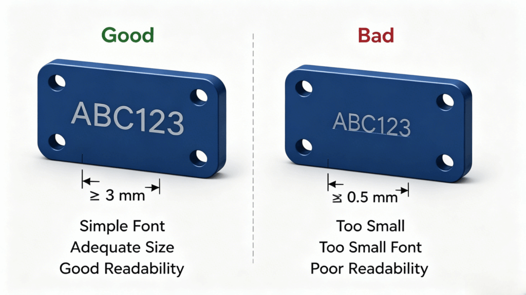
Engraved Text & Markings
Engraved logos, serial numbers, and identification markings can add value to finished parts but also increase machining time. For medium and high-volume production, laser marking is often a more economical solution than CNC engraving.
If CNC engraving is required, simple fonts and adequately sized characters should be used to ensure clear readability. Complex font styles, extremely small text, and excessive engraving depth should be avoided because they increase machining time and may compromise marking quality.
Best Practices When Designing Parts With CNC Machining
Different CNC processes including milling, turning and drilling have distinct characteristics. Targeted design optimizations for each process can maximize machining efficiency and part quality.
Best Practices for CNC Milling
Milling uses rotary round cutters to remove materials and form irregular shapes. It includes 3-axis to 12-axis equipment, and design optimization focuses on tool selection and feature geometry.
Use commonly available standard end mills as much as possible. Design all radii, slots and cavities to match standard tool sizes, which can greatly cut costs and shorten lead times.
Sharp internal corners are unachievable with round milling cutters. All inner corners must be designed with radii, and the radius shall be larger than half of the cutter diameter. Add transitional fillets where inclined surfaces connect with vertical walls.
Control the depth of narrow slots strictly according to materials. For plastic parts, the maximum slot depth is 15 times the cutter diameter; for aluminum, 10 times; for steel, no more than 5 times.
Design internal radii as large as possible. Larger radii support bigger rigid cutters and improve material removal efficiency. We suggest avoiding radii smaller than 0.8mm. It is better to set the part radius slightly larger than the cutter radius for a smoother tool path.
Best Practices for CNC Turning
CNC turning processes axisymmetric cylindrical parts on lathes. It delivers excellent surface finish and tight dimensional tolerances, and its design rules focus on symmetry and structural rigidity.
Avoid sharp internal and external corners for turned parts. Add round radii to corners or slightly incline side walls. Smooth continuous contours can be completed with a single lathe tool and reduce secondary operations.
Stay away from overly long and thin shaft parts. Such parts will spin unevenly and generate cutting chatter. The general length-to-diameter ratio for turned parts shall be kept at 8:1 or below. For extra-long workpieces, use center holes and tailstock support.
Maintain sufficient wall thickness for tubular turned parts. Thin walls will reduce structural rigidity and make tight tolerance control difficult. The wall thickness of turned sections is recommended to be more than 0.02 inches.
All main features of turned parts should be symmetrical around the rotating axis. Asymmetrical structures require complex clamping and multiple setups. If non-symmetrical features are necessary, minimize their quantity and size.
Best Practices for CNC Drilling
Drilling is dedicated to making circular holes. Drill bits have conical tips, so design rules must match the working characteristics of drill tools.
Limit the maximum drilling depth. Do not drill holes deeper than 12 times the bit diameter. Excessively long drill bits lose rigidity, leading to tolerance deviation and frequent bit breakage. If deep holes are required, enlarge the hole diameter appropriately.
Avoid partial holes on the edge of workpieces. The drill tip is easy to wander when cutting incomplete holes, resulting in poor roundness. If partial holes are inevitable, ensure most of the hole body is within the solid material.
Keep the drill axis perpendicular to the workpiece surface. Inclined surfaces will cause drill wandering and burrs. You can machine a shallow flat positioning plane on curved surfaces to ensure vertical drilling.
Do not arrange drilled holes to pass through existing internal cavities. If intersection is unavoidable, ensure the central axis of the hole keeps stable to prevent tool jamming.
ZH Precision Custom CNC Machining Service
Improper design will lead to defective parts, material waste and soaring costs. Choose ZH Precision for one-stop CNC machining solutions from prototype to mass production.
We are a professional manufacturer equipped with 3-axis to 5-axis CNC machines. Our team of experienced designers, engineers and machinists can handle parts of different complexities for various industries. We adhere to standardized CNC design rules and strict quality inspection procedures to guarantee fast delivery and stable part quality.
Upload your STEP, IGES or STP 3D drawings now to get a free quotation and professional design optimization suggestions.
Conclusion
Good CNC part design balances functional requirements and manufacturing feasibility. Most extra costs, long lead times and dimensional errors originate from unreasonable geometry, such as sharp inner corners, ultra-thin walls and over-tight non-critical tolerances.
By adhering to unified design limits for wall thickness, internal radii, hole depth ratios and thread sizes, you can avoid secondary processing, suppress cutting vibration and stabilize batch quality. Optimizing features separately for milling, turning and drilling further improves cutting efficiency and reduces tool wear.
Standardized, machinable designs bring clear benefits for both prototype testing and mass production, including lower manufacturing expenses, shorter delivery cycles and consistent dimensional accuracy of finished components.