In this guide, we’ve compiled eight core DFM considerations to keep top-of-mind when designing parts for CNC machining. Checking your design against this list before submitting it for manufacturing will help you save significant time and cut unnecessary expenses.
What Is DFM for CNC Machining?
Definition of DFM
Design for Manufacturing (DFM) refers to a set of design principles that optimize part geometry, features and dimensions to fit standard manufacturing processes, tooling and workflows. For CNC machining, DFM aims to make parts easier to machine while maintaining required performance and quality.
Why DFM Is Critical for CNC Manufacturing
Poor design choices often lead to frequent tool breakage, excessive machining passes, longer lead times, higher scrap rates and inflated production costs. By applying DFM rules at the design stage, engineers and designers can streamline production, improve surface finish and dimensional accuracy, and ensure consistent output for both prototypes and mass production.
Complete CNC Machining DFM Checklist (8 Key Design Checks)
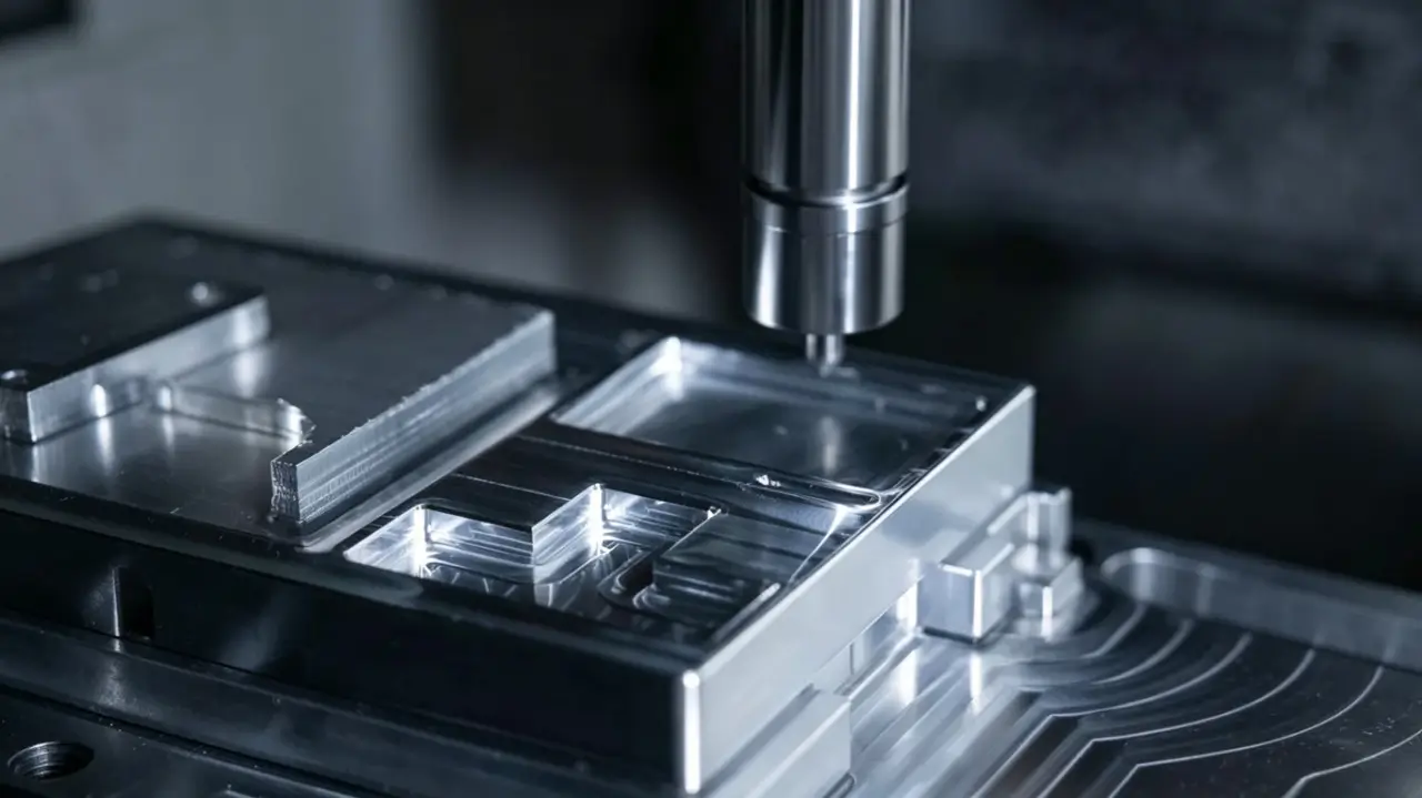
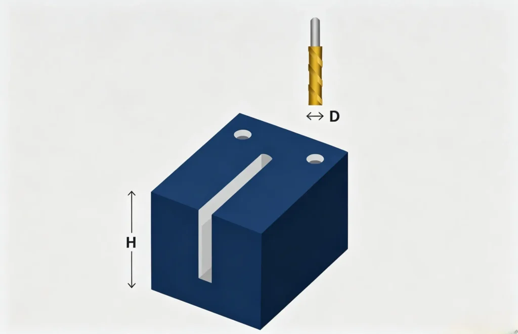
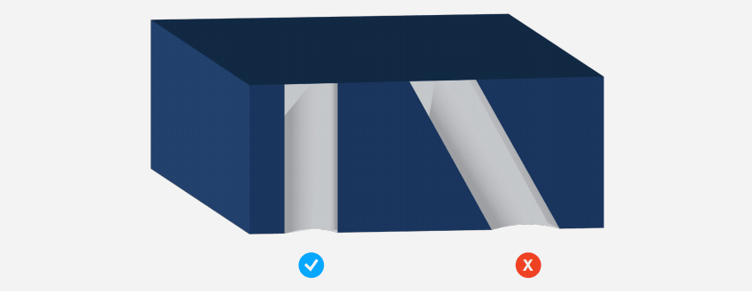
Deep & Narrow Pockets
Deep-narrow pockets or slots must be machined by longer tools, which are more prone to breakage and can cause chatter, or machine vibrations. Additionally, it takes several passes to machine a deep pocket, which drives up machining time and manufacturing costs.
Avoid designing parts with deep pockets whenever possible. If a deep pocket cannot be avoided, engineers and designers should decrease its depth as much as possible or increase the cross-section area of the pocket. Remember that you may need smaller tools to complete finishing passes. As a rule, pocket depth shouldn’t exceed 3x the diameter of the smallest tool needed for the final feature. For example, pockets should be no deeper than 1.5″ (38.1 mm) when using a 0.5″ (12.7 mm) cutter. Engineers may have to adjust this figure based on the material they are using and the tools that are available to them.
Narrow Regions & Tight Clearances
Narrow regions are difficult to manufacture because the size of the cutter is restricted by the smallest distance between the various faces of the feature. Long and small diameter cutters are prone to breakage and chatter.
Avoid designing features or faces that are too narrow for a cutter to easily pass through. If narrow regions cannot be avoided, they must not be too deep. Remember that the depth of any feature should be less than 3x the diameter of the smallest tool needed for the final feature. As a best practice, wall sections should be greater than 0.03″ (0.762 mm) thick. A shorter cutter with a larger diameter can also be employed to reduce chatter.
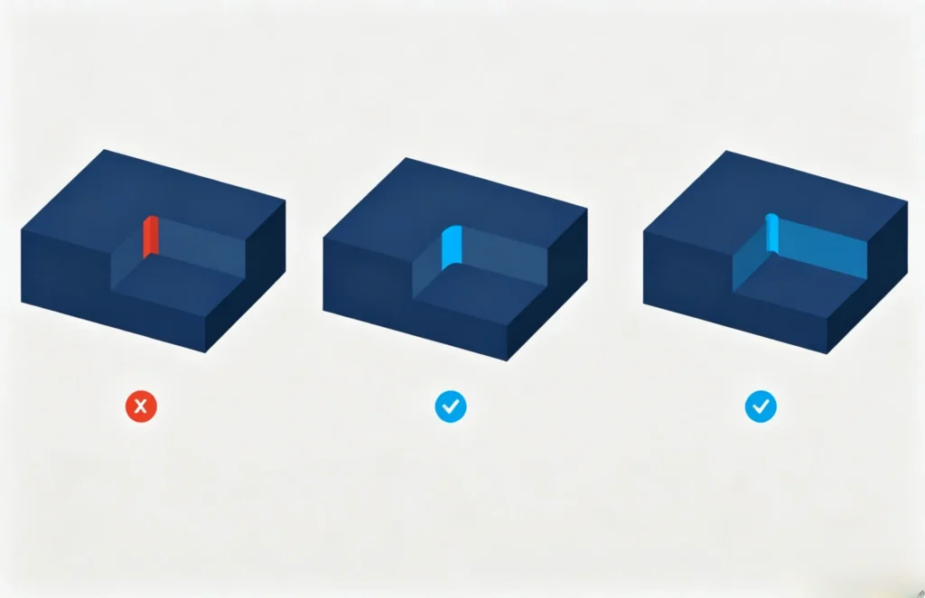
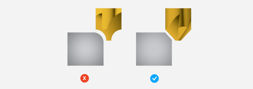
Sharp Internal Corners
Since all CNC drill bits are circular, it’s difficult to achieve sharp internal corners. Instead, the drill bit will leave behind a pocket of unmachined space called an internal corner radius. It’s possible to machine sharp internal corners using workarounds, like electrical discharge machining, but these methods tend to be expensive.
Avoid sharp inside corners whenever possible. Ideally, a corner radius needs to be slightly larger than the cutter. If a corner radius is the same diameter as the cutter being used to form it, it can cause chatter and premature tool wear.
Increasing the corner radius beyond the standard value by as little as 0.005″ (0.127 mm) can give the tool enough room to move around and follow a more circular path.
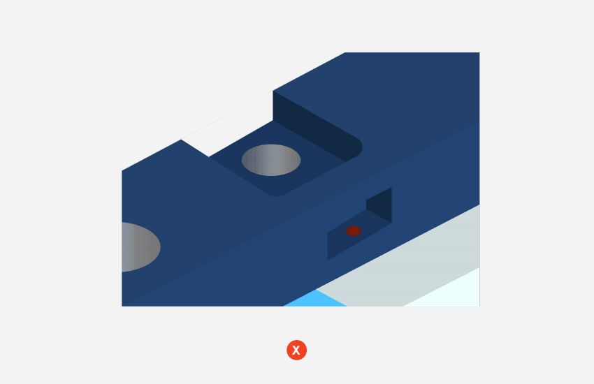
Inaccessible Machining Features
Inaccessible features like counterbores that open inside another pocket or pockets with negative drafts take longer to machine — if they’re even possible — because the cutting tool cannot easily access them, which in turn drives up costs.
You should ensure a cutting tool has full access to all features within a part without being blocked by another feature.
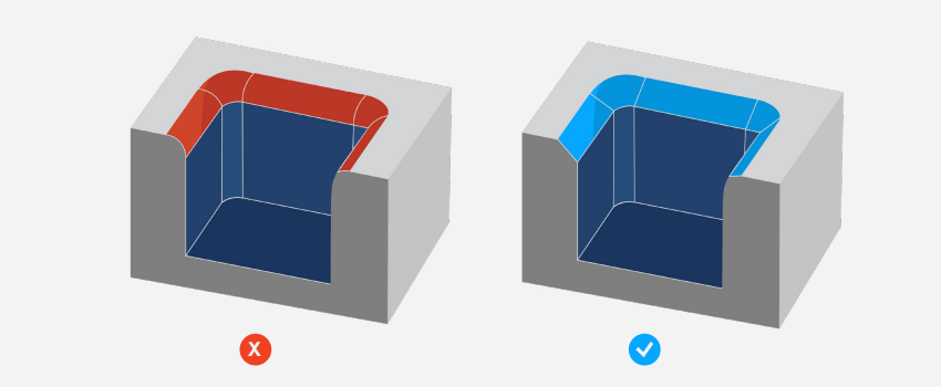
Unnecessary Outside Fillets
Outside fillets, or fillets on the top edges of pockets, bosses, and slots, require an exceptionally sharp cutter and a precise setup. Both of these requirements can be prohibitively expensive for some product teams. To avoid incurring these costs, bevel or chamfer, rather than fillet, the outside edges of features.
Too-Thin Part Walls
When it comes to CNC machining with metal, thin walls increase chatter, which can compromise the accuracy of the machining process and the surface finish of the part. With plastics, thin walls can cause warping and softening. As such, you should do your best to avoid designing parts with thin walls.
The ideal minimum wall thickness is 0.03″ (0.762 mm) for metals and 0.06″ (1.524 mm) for plastics. You may be able to achieve thinner sections without significant risk, but this needs to be assessed on a case by case basis.

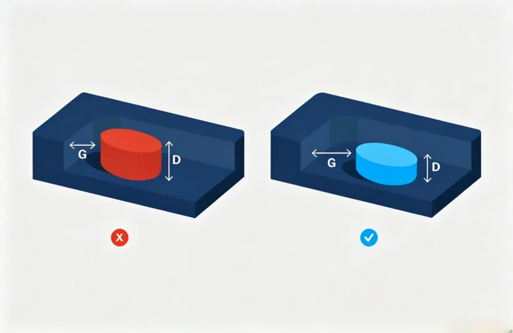
Flat-Bottomed Holes
Flat-bottomed holes require advanced machining operations and often cause problems down the line for subsequent operations like reaming. Avoid creating blind holes with a flat bottom — especially small holes — and instead use a standard twist drill to create holes with cone-shaped bottoms. Cone angles are commonly 118° or 135°.
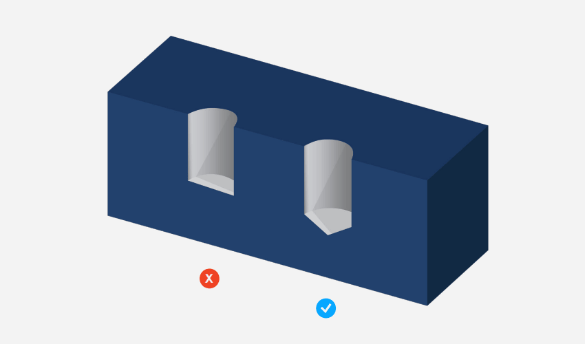
Improper Drill Entry & Exit Angles
A drill tip will wander when it comes into contact with the material’s surface if that surface isn’t perpendicular to the drill axis. Uneven exit burrs around the exit hole will also make removing the burr difficult. To ease entry and exit, avoid designing hole features with start and end faces that are not perpendicular to the drill’s axis.

Material-Specific DFM Guidelines (Metal vs. Plastic)
Material properties play a vital role in CNC DFM, as different materials react differently to cutting force, heat and tool contact. Standard design rules need proper adjustments based on your selected material.
For metal parts, harder alloys demand more rigid tooling and slower cutting speeds. Stick strictly to the 3:1 depth-to-tool-diameter ratio, and keep wall thickness above the recommended minimum to prevent deflection and vibration. Extra attention should be paid to sharp edges, as metal burrs are harder to remove.
For plastic parts, heat generated during machining may lead to melting, warping or surface damage. Avoid overly thin walls and long, slender features. Use larger radii on corners to reduce stress concentration, and keep cutting features simple to minimize heat buildup.
CNC Machining Tolerance DFM Best Practices
Unnecessarily tight tolerances are one of the most common cost drivers in CNC machining. Tight tolerances require slower cutting speeds, multiple finishing runs and strict quality inspection, all of which extend lead time and raise costs.
Follow standard industry tolerances for general non-mating features. Reserve tight tolerances only for critical assembly surfaces and functional areas. Clearly mark tolerance requirements on your drawings, and communicate with your manufacturer if you have special precision demands. Reasonable tolerance settings will balance part performance and production efficiency.
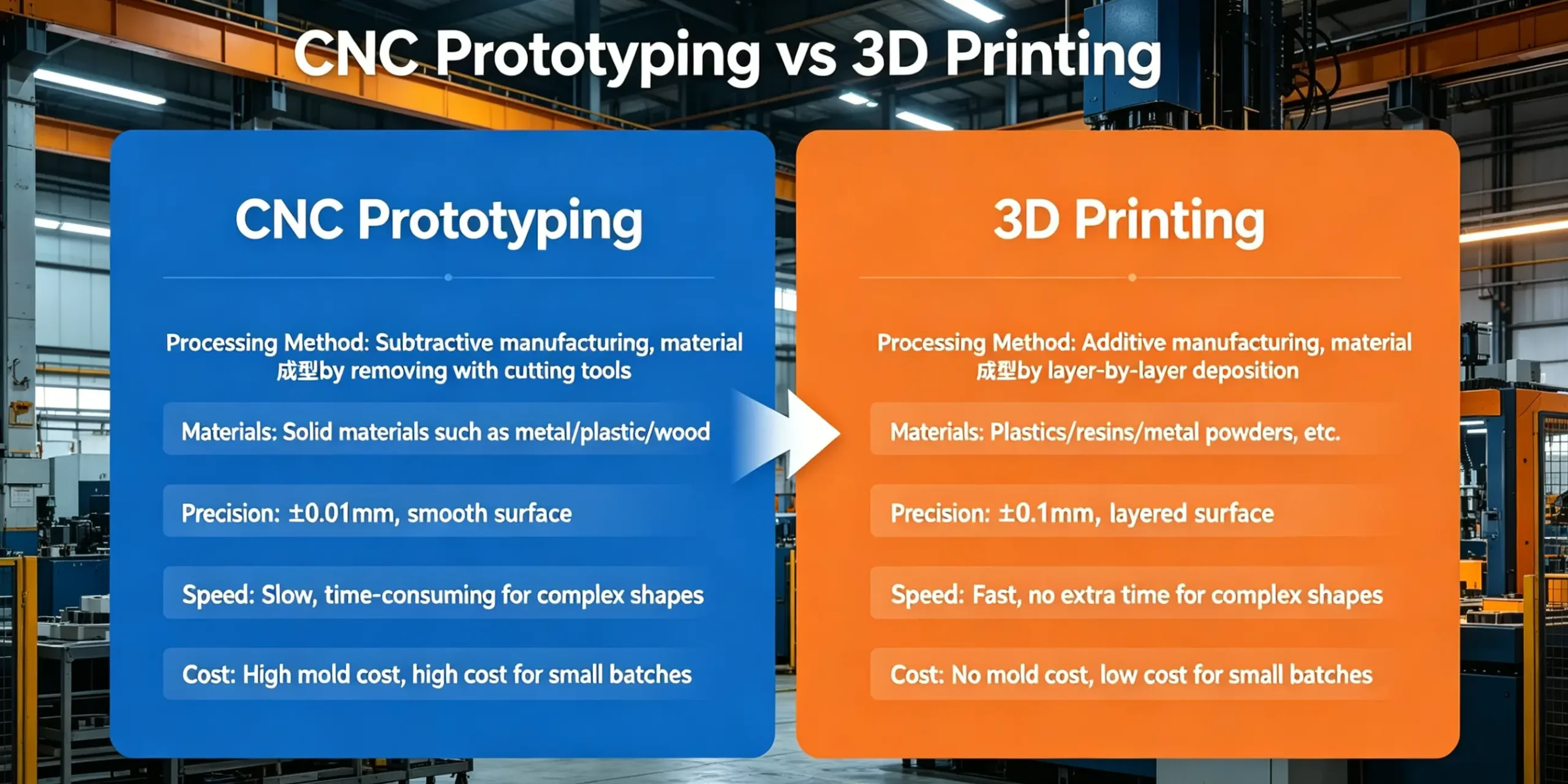
DFM Differences: Prototyping vs. Mass Production
DFM standards vary greatly in the CNC prototyping process and high-volume mass production.
During the CNC prototyping process, designers can accept slightly more complex features, as the priority is to verify design functionality. Some special structures that are not ideal for mass machining can be applied temporarily.
For mass production, DFM rules must be followed strictly. Designs need to focus on stable machining, easy tool changing, fast cycle time and low scrap rate. Simplify complex features, standardize hole sizes and radii, and make the design fully compatible with automated production workflows.
Common CNC DFM Mistakes Engineers Make
Many design issues arise from overlooking basic CNC machining limitations. Below are the most frequent mistakes to watch out for:
1.Designing ultra-thin walls and extra-deep narrow pockets beyond standard tool limits.
2.Retaining sharp internal corners without adding proper radii.
3.Creating holes on non-perpendicular surfaces, leading to drill deviation.
4.Specifying overly strict tolerances on non-critical features.
5.Adding complicated external fillets that increase machining difficulty.
6.Designing hidden or blocked features that tools cannot reach.
Review your design against these points before production to eliminate avoidable problems.
Professional DFM & CNC Machining Services
While this checklist covers core DFM principles, complex projects often require professional experience and customized solutions. An experienced manufacturing partner can offer tailored insights to perfect your design.
At ZH Precision, our team helps engineers and designers follow strict DFM standards. We utilize advanced design tools to optimize your parts for superior manufacturability and consistent quality.
We deliver one-stop metal manufacturing solutions covering CNC machining, aluminum/zinc/magnesium die casting, sheet metal fabrication and aluminum extrusion. We work with aluminum, zinc, magnesium alloys, stainless steel and carbon steel. Let’s create reliable metal parts together. Contact us today to get started.
Conclusion
Design for Manufacturing is a fundamental practice to streamline CNC machining. This guide has covered core DFM definitions, eight key design checks, material guidelines, tolerance rules, the differences between prototyping and mass production, and common mistakes to steer clear of.
Always tailor your designs to actual machining capabilities and material properties. Following these standards will help you cut costs, minimize errors and shorten lead times, delivering reliable, production-ready parts efficiently.
FAQ
A:Sharp internal corners are unachievable with standard CNC round cutters, which is why internal corner radii are essential. The ideal practice is to set a corner radius slightly larger than the used cutter size. A small increase of 0.005 inches helps tools move smoothly, reduces chatter and tool wear, and avoids costly secondary machining processes like EDM for metal parts.
A:Yes, DFM standards vary greatly between prototyping and mass production. For one-off prototypes, minor complex features can be tolerated to verify design functionality. For mass metal production, designs must prioritize simplicity, standardized dimensions, and tool accessibility to reduce cycle time, lower scrap rates, and ensure consistent batch quality across aluminum, steel, and alloy parts.
A:As a general CNC machining rule, the depth of pockets and slots should not exceed 3 times the diameter of the smallest finishing tool. Deeper structures require longer, thinner cutters that easily vibrate and break, resulting in poor precision and longer machining cycles.
A:For most metal materials including aluminum, stainless steel, and magnesium alloys, the recommended minimum wall thickness is 0.03 inches (0.762 mm). Thinner walls are prone to deflection, chatter, and deformation during high-speed cutting, affecting overall accuracy and flatness.
A:For mass production, designers should standardize corner radii, avoid complex external fillets, eliminate unreachable features, and use reasonable tolerance ranges. Simplifying tool paths, reducing cutting steps, and following strict DFM rules can stabilize quality, lower scrap rates, and make long-term production more cost-effective.